

A large-scale cleanroom ceiling system is much more than a simple suspended ceiling.
For clean manufacturing facilities, the ceiling must support multiple components while maintaining structural stability, accurate elevation, airtightness and a controlled installation environment.
A typical system can consist of:
Secondary steel support frame
Aluminum T-bar ceiling grid
Cleanroom blank panels
FFU fan filter units
Air filters
Suspension rods and adjustable hangers
Airtight sealing components
In this project configuration, the secondary steel frame transfers the loads from the T-bar grid, FFUs and blank ceiling panels to the building structure.
The FFU arrangement and quantity can then be configured according to different cleanroom cleanliness requirements.
This article explains the complete construction process of a large cleanroom ceiling, from initial setting-out to final FFU installation.
The overall construction sequence is:
Drawing review and technical briefing → Site reference verification → X/Y axis and elevation setting-out → Threaded rod fabrication and suspension point installation → Secondary steel frame installation and leveling → T-bar grid ground pre-assembly → Overall T-bar lifting, alignment and fine adjustment → Perimeter grid installation → Sealing strip application and blank panel installation → Clean-area environmental control → Fresh-air purging → FFU and filter installation
Following the correct sequence is important because each stage affects the accuracy and cleanliness of the next step.
For large cleanroom projects, ceiling installation should therefore be treated as an integrated engineering system rather than several independent installation tasks.
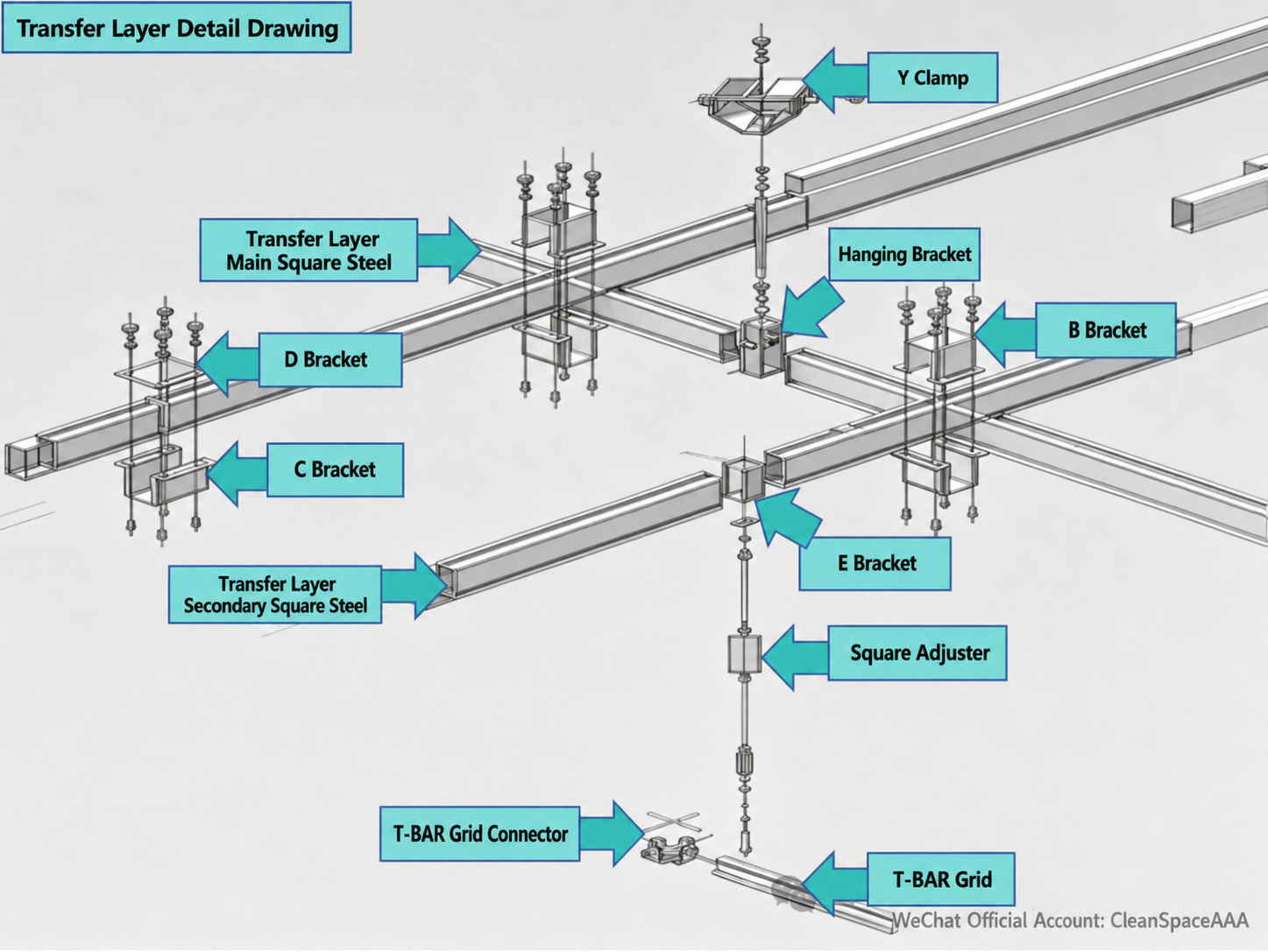
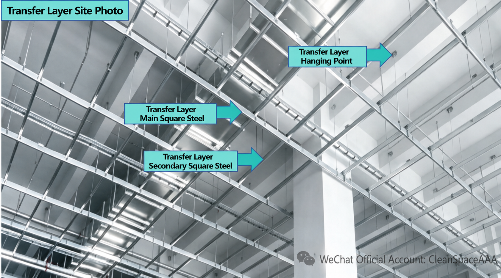
For this type of T-bar cleanroom ceiling, a secondary steel support frame, also referred to as a ceiling conversion layer, is normally installed above the ceiling grid.
The T-bar grid itself should not directly carry the entire ceiling load from the building slab.
Instead, loads from the:
T-bar ceiling grid
FFU fan filter units
Cleanroom blank panels
are transferred to the secondary steel structure.
The secondary frame is then connected to the main building structure through threaded suspension rods.
According to the construction requirements in this project, the T-bar grid should not simply be suspended directly from threaded rods fixed to the floor slab without the secondary steel support structure.
The secondary support structure uses hot-dip galvanized square steel sections.
The specified sizes are:
Main steel member:
120 × 50 × 5 mm square steel
Secondary steel member:
100 × 50 × 2.3 mm square steel
The steel members form a structural grid above the cleanroom ceiling and provide the main support platform for the suspended T-bar system.
Before steel installation begins, the required ceiling elevation must be established according to the building construction reference level.
Laser levels and surveying instruments are used to check elevations throughout the installation area.
A unified elevation line is then marked on:
Walls
Columns
Other suitable structural reference surfaces
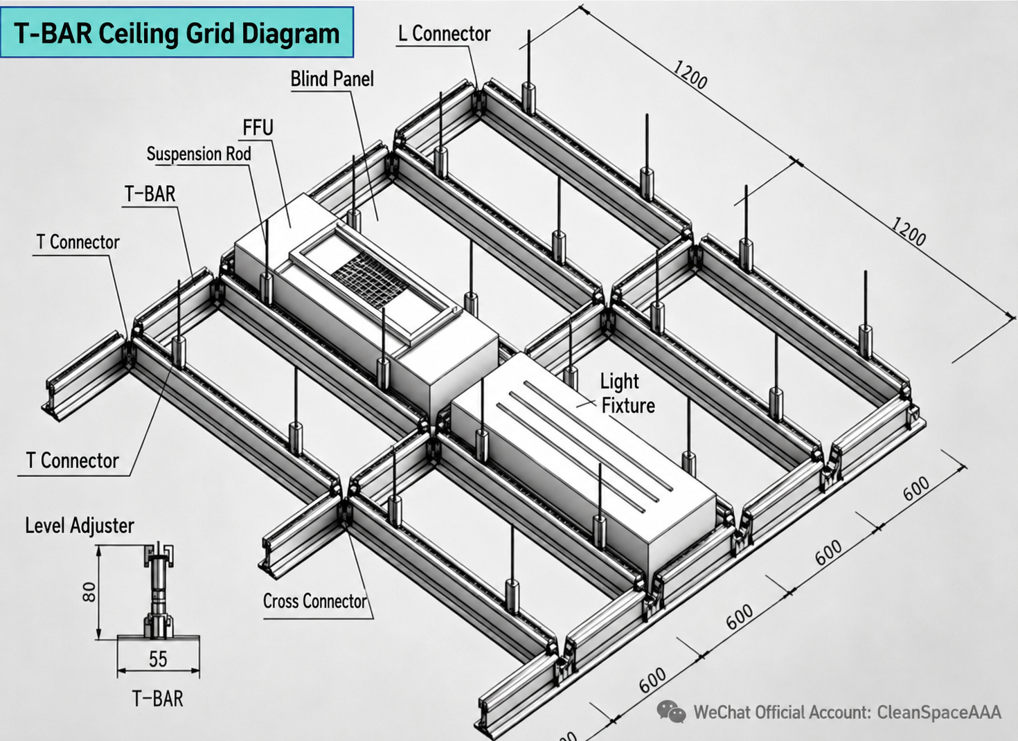
After the elevation is confirmed, the X/Y grid lines are set out using a 1200 mm module.
Accurate setting-out at this stage is essential because the steel support frame, T-bar grid, blank panels and FFUs must ultimately align with the same ceiling module.
The length of each threaded suspension rod is determined according to the distance between the building structure and the required elevation of the secondary steel frame.
Each rod is prefabricated according to the required installation height.
At the upper and lower ends, the threaded rods are secured using:
Double nuts + flat washers + spring washers
This connection method helps maintain a stable suspension connection during installation and subsequent adjustment.
The main steel beams are installed continuously according to the building structural direction or project design.
Where main beams are connected or spliced, suspension support points must be provided.
Secondary steel members are installed perpendicular to the main steel members.
Together, they form a standard rectangular support grid for the cleanroom ceiling system.
According to the project requirements:
Horizontal deviation of square steel: ≤ ±5 mm
Suspension point spacing: 1200 mm ±5 mm
Accurate control of the secondary frame is essential because deviations at this level will be transferred to the T-bar ceiling below.
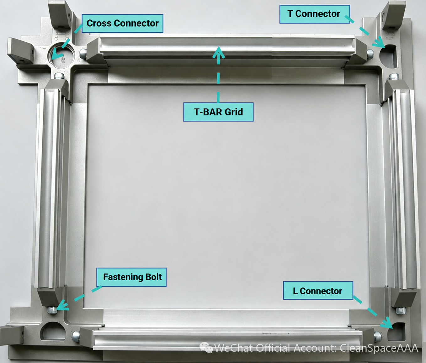
The cleanroom T-bar grid is manufactured from aluminum alloy.
The system includes different connecting components such as:
Cross connectors
L-shaped connectors
T-shaped connectors
Installation should be completed in a controlled sequence.
Suspension rod lengths are prefabricated according to:
Finished ceiling elevation
Secondary steel frame elevation
Square adjusters and anti-slip washers are assembled in advance.
Using standardized components and consistent elevations helps reduce excessive ceiling flatness deviations during large-area installation.
After the secondary steel structure has been completed, the centerlines of the T-bar grid and the suspension point locations are marked on the steel frame.
A trial row of suspension points should be installed first.
Its elevation and modular spacing are checked before full-scale installation begins.
Only after the trial section is confirmed should construction proceed across the entire ceiling area.
One of the important construction methods in this system is ground pre-assembly.
The T-bar grid should not be individually aligned and assembled piece by piece at high level.
Instead, the main and secondary T-bars are pre-assembled into standard ceiling grid sections on the ground.
All joints should be properly connected and secured.
During pre-assembly, the protective film should remain on the aluminum profiles to reduce:
Surface scratches
Dust accumulation
Construction contamination
This method can also improve installation efficiency for large cleanroom ceilings.
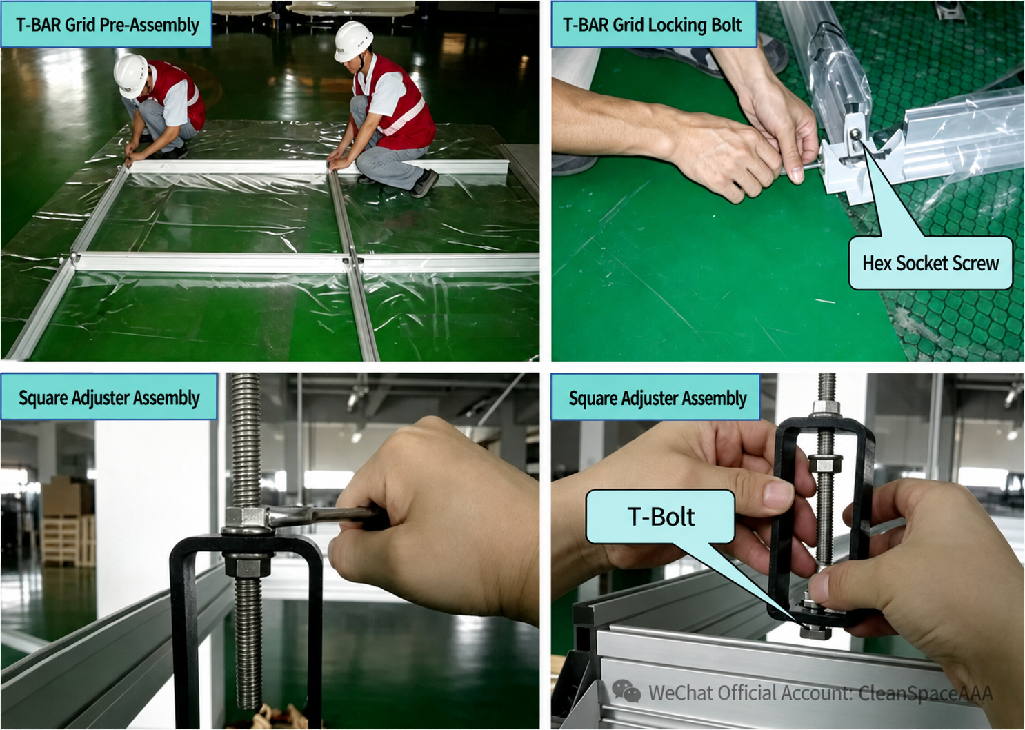
After a complete grid section has been assembled, it is carefully lifted to the required ceiling elevation.
The grid is then connected to the square adjusters on the secondary steel frame using T-shaped bolts.
According to the project requirements, the square adjuster is installed approximately 150 mm away from the center of the T-bar cross joint.
The anti-slip nuts are then tightened to complete the initial fixation.
After initial suspension, the entire T-bar ceiling grid must be accurately aligned.
Plumb tools and laser instruments are used to verify the centerlines of the T-bar grid intersections.
The overall axial deviation should be controlled within:
1 mm
Accurate grid alignment is especially important because FFUs and blank ceiling panels must fit correctly into the finished ceiling openings.
A rotating laser level is used to fine-adjust the T-bar system span by span.
The horizontal deviation for an individual grid span should be:
≤ 3 mm
The overall T-bar ceiling elevation is also preset approximately:
3–5 mm above the design elevation
This allowance is intended to compensate for later settlement after the cleanroom blank panels and FFUs are installed.
At walls and columns, the standard T-bar module may not perfectly match the remaining ceiling dimensions.
Non-standard perimeter profiles are therefore required.
These perimeter components should be customized according to the actual site dimensions.
After the perimeter profiles are installed, the entire T-bar ceiling should be checked and adjusted again to confirm:
Elevation
Grid alignment
Flatness
Connection accuracy
After the T-bar grid has been accurately installed and leveled, the next stage is the installation of cleanroom blank ceiling panels.
The specified blank panels in this system are custom-made from painted steel sheet with folded edges on all four sides.
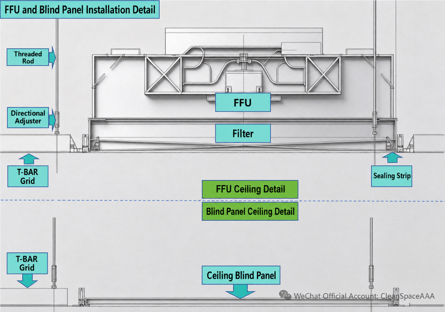
Before installation, the corresponding airtight sealing strip is applied.
The panels are then placed into the T-bar grid.
After each blank panel is positioned, dedicated blank-panel clips are installed to press the panel securely into place.
The purpose is to ensure that the sealing strip remains tightly compressed against the T-bar flange.
This creates a continuous seal between the ceiling plenum and the cleanroom below.
Proper sealing helps prevent uncontrolled airflow between the cleanroom and the ceiling plenum.
For irregular ceiling areas, non-standard panels may be required.
According to the project requirements, non-standard blank panels with a width greater than 200 mm on one side should not be cut manually on site.
Instead:
Measure the actual ceiling opening.
Confirm the required panel dimensions.
Produce the non-standard panel at the factory.
Deliver the finished panel for site installation.
Factory fabrication helps maintain dimensional accuracy and consistent edge treatment.
The FFU installation stage requires stricter cleanliness control than the earlier structural installation stages.
According to the project process, FFU installation should begin only after the workshop has entered the specified Level 4 clean-control stage.
Before installation, the fresh-air system should continuously purge the cleanroom for at least:
24 hours
Tools and equipment entering the clean area should also be thoroughly wiped and cleaned to prevent construction dust from contaminating the cleanroom.
During filter installation, the filter is passed through the opening at approximately a:
45° angle
The filter must be handled carefully.
Installers should avoid touching the filter paper or filter media.
After the filter and FFU housing are correctly aligned, the unit should be lowered slowly into position.
Sealing strips are then used to fill and seal the required gaps.
After all FFUs have been installed, electrical connections are completed.
The system is then energized for trial operation.
During commissioning, installers should check:
Fan vibration
Airflow uniformity
Air leakage
Abnormal operating noise
Any abnormal conditions should be corrected before the ceiling system is considered complete.
Large-area cleanroom ceiling systems require strict quality control throughout construction.
Several installation details are particularly important.
Steel structures, ceiling profiles and accessories should use the specified finished materials, such as hot-dip galvanized or anodized components.
Rusty untreated ferrous components should not be introduced into the cleanroom construction area because corrosion products can create contamination risks.
Protective film, construction debris or other foreign materials must not become trapped inside T-bar joints.
Connections should remain flat, tight and accurately aligned.
Poorly assembled joints may create excessive gaps or grid misalignment.
During installation, contractors must continuously check:
Ceiling elevation
X/Y axis position
Grid alignment
Surface flatness
Ignoring these parameters at an early stage can result in large-area ceiling deformation after FFUs and panels are installed.
Airtight sealing strips must be installed continuously.
They should not contain:
Breaks
Overlapping sections
Excessive compression
Deformation
Consistent sealing is essential for maintaining separation between the cleanroom and ceiling plenum.
Clean-area construction should follow strict dust-control procedures.
Completed components should also be protected and covered where necessary to prevent contamination or damage before final commissioning.
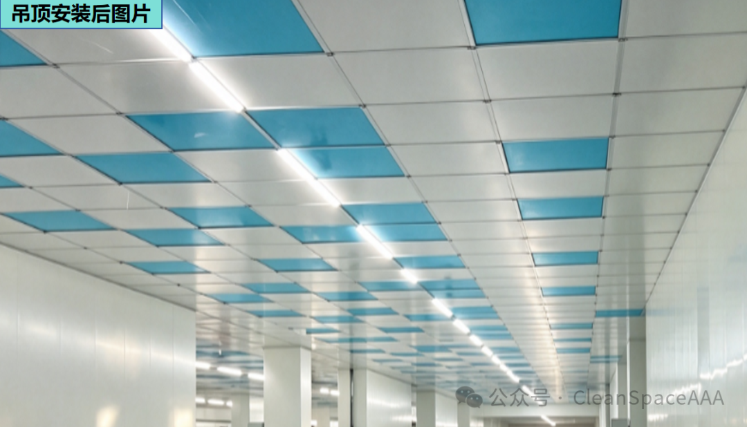
A large cleanroom ceiling combines structural, architectural and air-filtration functions within a single overhead system.
The secondary steel structure carries the load.
The T-bar grid defines the ceiling module.
The blank panels create sealed ceiling surfaces.
The FFUs provide filtered airflow.
For this reason, problems with structural elevation, grid accuracy, airtightness or cleanliness during installation can affect later stages of the project.
A systematic construction sequence is therefore essential.
From the secondary steel support frame and T-bar grid to blank panels and FFU installation, each component should be coordinated according to the same ceiling layout and quality-control requirements.
For electronics, pharmaceutical, food processing, semiconductor and other controlled-environment facilities, the cleanroom ceiling is a critical part of the overall cleanroom construction system.
A properly installed system should combine:
Stable secondary steel support
Accurate T-bar ceiling grids
Airtight cleanroom blank panels
Correctly installed FFUs and filters
Precise elevation control
Controlled installation cleanliness
For large industrial cleanroom projects, careful coordination between structural installation, ceiling construction and FFU installation can help achieve a more stable and maintainable cleanroom ceiling system.
We provide cleanroom ceiling materials and system solutions for industrial cleanroom projects, including T-bar ceiling grids, cleanroom panels, FFU systems and related cleanroom components.
If you are planning a cleanroom project, you can send us your:
Cleanroom layout drawings
Ceiling height
Ceiling area
FFU layout
Required panel dimensions
Project application
Our team can provide a suitable cleanroom ceiling solution based on your project requirements.
This article is from the WeChat official account: CleanspaceAAA (it will be removed immediately in the event of any infringement)
 EN
EN
 AR
AR
 NL
NL
 FI
FI
 FR
FR
 DE
DE
 EL
EL
 HI
HI
 IT
IT
 JA
JA
 KO
KO
 PT
PT
 ES
ES
 RU
RU
 TL
TL
 ID
ID
 UK
UK
 VI
VI
 TH
TH
 HU
HU
 TR
TR
 MS
MS
 LA
LA
 BN
BN
 MN
MN
 MY
MY
 UZ
UZ
 KK
KK

